Español US
  English CA
  Français CA
  English US



SKU
W-4PSB-KIT
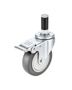
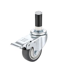
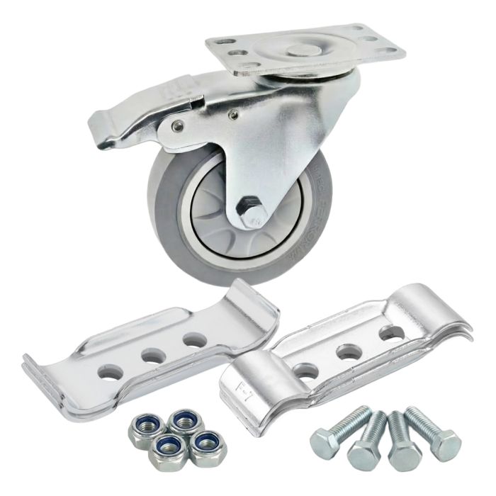
Kit de ruedas giratorias de 4" sobre placa con freno
- Hardware incluido
- Rueda de 4 pulgadas (100 mm) de diámetro
- 250 libras (113 kg) de capacidad de carga
- 2,5M/h de velocidad máxima
Also Available:
24,22 USD$

La rueda giratoria con montaje en brida es un soporte que añade movilidad a una aplicación y normalmente se monta en el extremo o el lateral de un perfil en T usando una placa base. El giro permite un movimiento fácil y giros de pivote. El freno de montaje superior bloquea tanto la rueda como el movimiento giratorio. Esto es ideal para usarse en entornos industriales como carritos móviles y soluciones de manejo de materiales.
- Rueda giratoria con placa y freno de bloqueo, equipada con rodamiento de bolas de precisión
- Capacidad de carga de 250 libras (113 kg)
- Velocidad máxima de 2.5 M/h (4.02 Km/h)
- El kit incluye: (2) Soportes de rueda superior (WF-UP), (2) Soportes de rueda inferior (WF-LOW), (4) Tornillos M8 x 35 mm (M8-35B) y (4) Tuercas M8 (M8-N).
| Box Quantity | 40 |
|---|---|
| Altura | 5 1/8 in (130 mm) |
| Ancho | 1 1/8 in (29 mm) |
| Weight (kg/lbs) | 1.884 lb (0.855 kg) |
| Dimensiones de la caja | Caja de cartón de 18 X 11 X 12 in (460 X 280 X 300 mm) |
| Material primario | Caucho termoplástico (TPR) |
| Resistencia a la temperatura | -22°F a 158°F (-30°C a 70°C) |
| Conductividad eléctrica (ESD) | No |
| Capacidad de carga máxima | 250 lb (113 kg) |
- Asegúrate de tener las siguientes piezas:
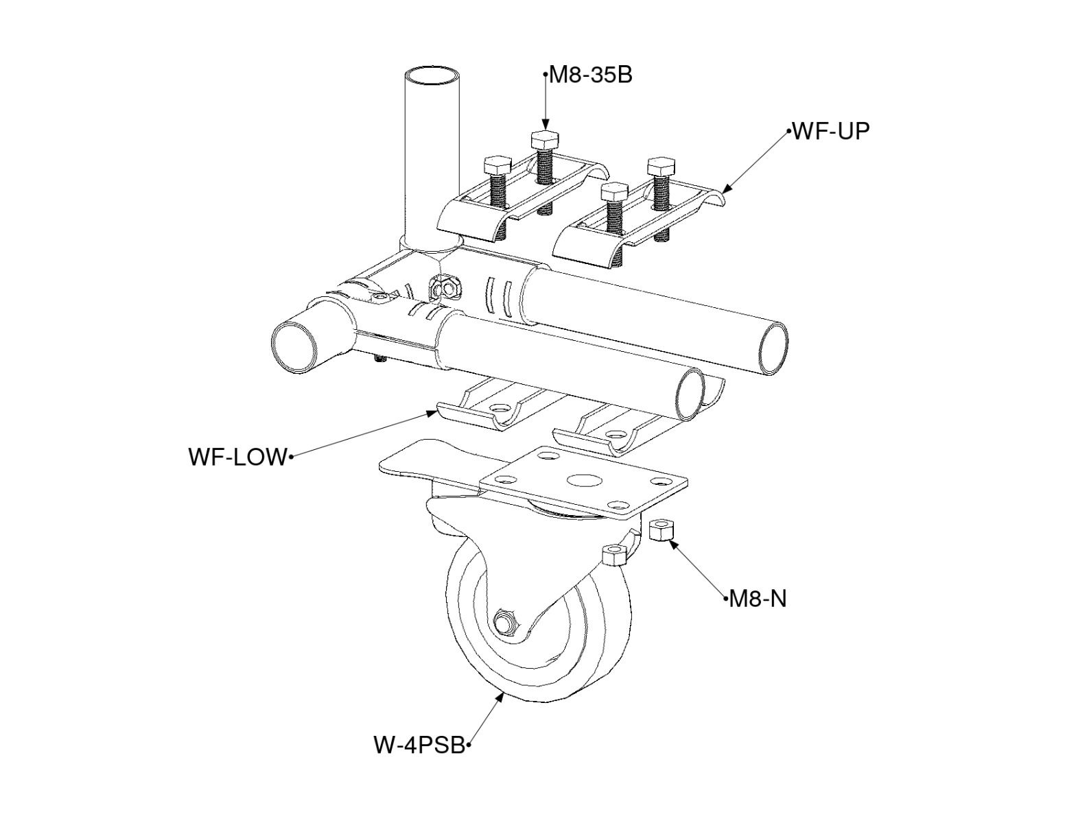
- 1x W-4PSB
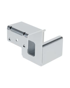
- 2x WF-UP
- 2x WF-LOW
- 4x M8-35B
- 4x M8-N
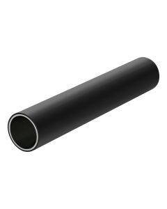
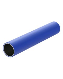
- 2x 28mm pipes of your choice
- 1x Wrench
- 1x Ratchet
- Asegúrese de que la estructura esté nivelada cuando esté sostenida por las tuberías que se rodarán. De lo contrario, la diferencia de altura podría hacer que la estructura se balancee.
- Asegúrese de que las tuberías estén paralelas y tengan 3 1/4 pulgadas de espacio de centro a centro.
- Coloca los dos WF-LOW perpendiculares sobre las tuberías.
- Coloca el rodillo en ambos WF-LOW y alinea las aberturas.
- Toma un WF-UP y regrúpalo con uno de los WF-LOW.
- Tome dos pernos M8-35B y dos tuercas M8-N e insértelos en las aberturas correspondientes. Luego, apriételos ligeramente juntos.
- Repita los pasos 6 y 7 para el otro WF-UP y los pernos y tuercas restantes.
- Ajuste completamente los cuatro pernos M8-35B y las cuatro tuercas M8-N en un patrón cruzado.
products you may also need